Nodes
A discrete function that executes within a flow. The function can be an action or a decision, which forms the basis of the flow's business logic.
Each node contains specific configurable properties, which appear when you double-click that node. You can then configure those properties with appropriate data.
Once a node is configured, you can connect it to other nodes in a logical sequence using connectors and create the flow. If you delete a node in a flow, the immediate connectors attached to the node are also deleted and you need to reconstruct the flow.
List of Nodes
The following table lists the nodes depending on the type of flow:
Adding a Node to Flow Canvas
Nodes are available in the Node Palette. Nodes are classified into different categories for easy identification based on their configurable properties. A few key points about nodes are that:
- You can drag-and-drop a node from the Node Palette onto the Flow Canvas. When dropped, the node snaps to the canvas grid.
- You can click any node on the canvas to select it.
- You can drag a selected node to an empty position on the canvas grid and re-arrange it. However, you cannot drop it on another node.
- You can double-click any node on the canvas to bring up the Node Configuration dialog box.
Node Configuration
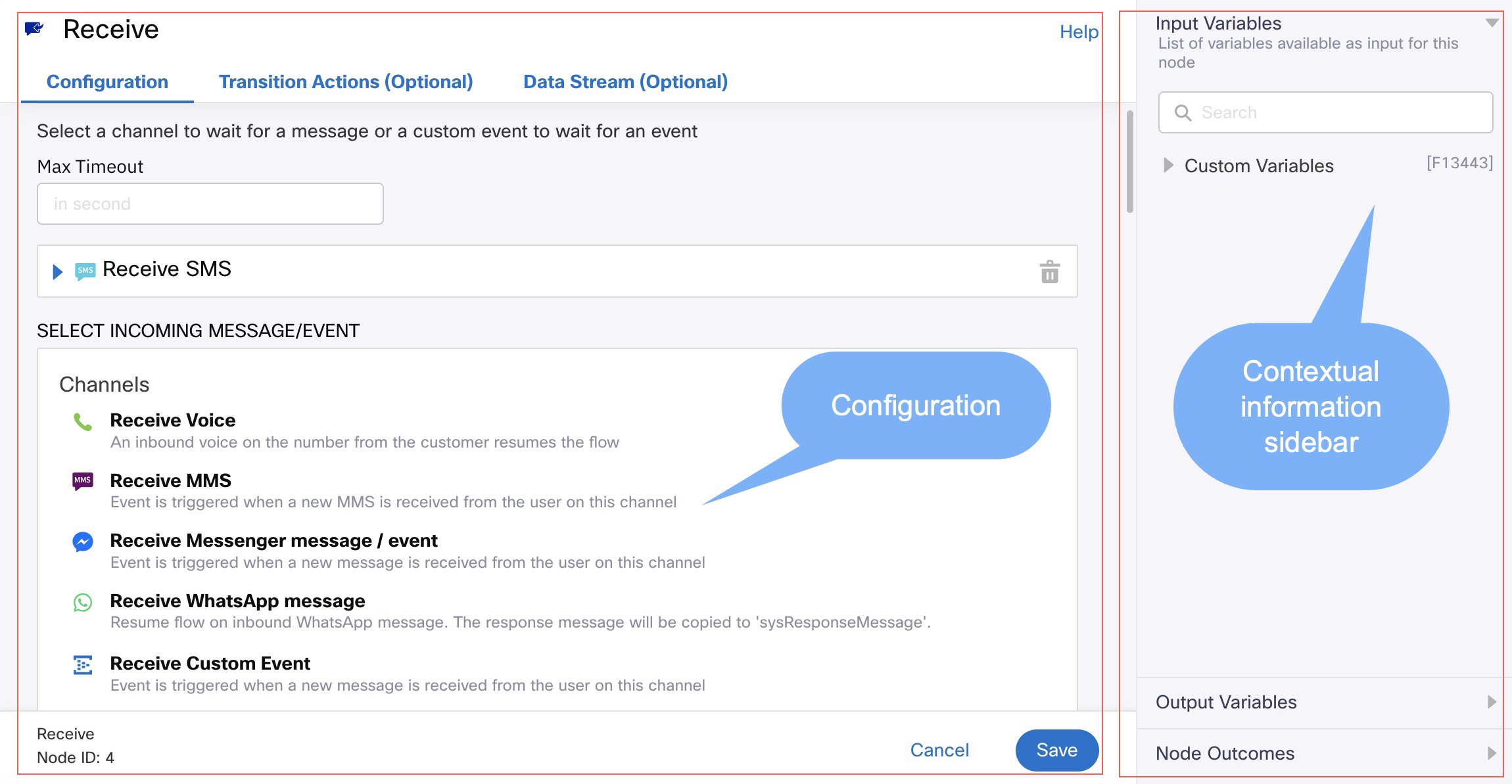
The Node Configuration dialog box appears with a split-screen view.
- The main area of the dialog box is dedicated to configuration.
- The split view on the right presents contextual information related to the node configuration.

Screenshot of Node Configuration Page.
Configuration Area
It consists of three tabs:
- Configuration: the main tab (default view) lists all the mandatory and optional fields required for configuring the node.
- Transition actions: this tab lists the node transition actions, that is actions to be performed by the flow while entering/leaving this node. A transition action can be configured to run on entering a node or while exiting a node. For more information, see Node Transition Actions.
- Data Streams: this tab lists all the data streams configured for the node.
Contextual Information Sidebar
The sidebar presents contextual node data for use within the main configuration area. The following information is available in the node sidebar:
- Input variables: list of all variables available as input to this node. It lists all nodes that are directly connected to this node. You can search for variables by their name.
- Output variables: list of output variables of this node. The list is updated based on the node configuration.
- Node outcomes: list of all possible outcomes. The outcomes can be one or more, depending on the node type and the data supplied during run-time. You can connect a node outcome to the next node or configure it to terminate the flow. You can customize the node outcome text for display on the flow canvas as the Connector Label.
Connectors
You can connect any two nodes in a flow using the connectors. You can connect a node outcome to the next target node, establish a connection, and pass the control to the next node.
A node can have multiple incoming connectors. The number of outgoing connectors for a node is defined by the node outcomes.
Drawing a Connector
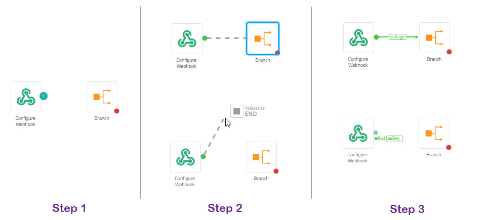
- Hover over a node and select the output edge to start drawing a connector. A connector appears when you point, hold, and drag a node outcome towards a target node.
- Drop the connector onto an empty space in the canvas to terminate the flow when that particular outcome is encountered. This brings up the configuration for the End Node. While trying to connect an event to the target node, the target node is highlighted.
A dotted line appears until you connect the outcome to the next node. After the outcome is connected to the target node, the dotted line turns into a continuous line with the Connector Label.
If a node output edge has multiple outcomes mapped to it, you will be prompted to select the applicable node outcome.
The following figure illustrates the steps to draw a connector:

Connecting Nodes in a Flow
Restrictions
A few restrictions apply while drawing connectors:
- You must configure a node to end the flow if it does not have an outgoing edge.
- You cannot loop back to the immediate previous node.
Deleting a Connector
To delete a connector, double-click it and select the connector, and then press the Delete button on the keyboard. When you delete a connector, it is removed from the flow canvas.
Connector Colour
To easily understand the flow, the Webex Connect platform supports the color-coding of the outcomes along with the corresponding connectors to match the three-node edges.
| Connector Colour | Indication |
|---|---|
| Green | Indicates the flow continuation outcome of the node For example: OnMessageSent |
| Orange | Indicates time-bound events of the node For example: OnTimeOut |
| Red | Indicates the error events of the node For example: OnDeliveryFailure |
Updated 8 months ago
